Posts Tagged ‘gadgets’

h1

Beagles in Paris

September 24, 2014

I’ve been working on a way to demonstrate a networking feature. I should tell you all about the networking feature but let’s just pretend that, like all routing protocols, we don’t really care about how it works.

Actually, that is why it is hard to demo networking protocols: either the demos do something and everyone says, “oh, I could do that over TCP/IP” or they don’t have any interface other than wireshark and everyone says, “wow, I’m bored.”

Yeah, I’ve been working in networking and missing my microprocessors quite a lot.

ANYWAYS… the demo! I have:

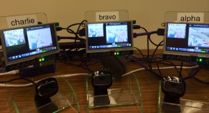
  • 8 BeagleBone Black, rev Cs
  • 8 LCD screen capes (these are absolutely marvelous)
  • 8 Webcameras
  • 8 brochure stands
  • 2 100W power supplies (each feeding four units, 5V 2A)
  • 1 hub to rule them all
  • 1 laptop to run the obligatory wireshark
  • Assorted cables (Power, Ethernet, one USB for config/debug)

We’re running something that acts like Dropbox so they all share the same data. (Seriously, I could tell you how but I’d use phrases like “Bit Torrent for the Internet” and get dirty looks from my workplace or crossed eyes from you.)

Before I go on with a few details about the build, how would you demonstrate Dropbox? As a walk-up, show-n-tell style demo on a crowded expo floor? Something that makes sense once you use it is remarkably complex for a demo.

For my demo, every second, each BBB takes a picture. It displays it on its screen and puts it in the shared directory. In another window, it uses a slideshow program to look at all of the pictures in the shared directory. Think of it like a security system, I show you what I see and what everyone else sees. This setup lets people see the how fast files are sync’d and the Ethernet traffic that passes on the wire to implement the protocol (look wireshark, no TCP traffic!).

Beagles

The main difficulty I have working with the single board computers like BBB and Raspberry Pi is that I don’t know the overly crowded space. Good software might have terrible websites, yet vaporware always looks real. It took me a multiple hours of research and testing to settle on streamer to take still pictures and on feh to display them.

For the most part I used three units to do the setup and testing. Eventually, I got it working well-enough to go ahead and set up on all eight units. That was when most of the problems actually showed up, of course.

My pictures kept getting overexposed. They’d start out ok but get lighter all the time until all images turned white if the system was left alone. Of course, it took some time to figure out that the exposure setting was the problems since if I interacted with the units, it took much longer to get to white. Eventually I searched for possible causes, downloaded v4l-utils so I could try v4l2-ctl which communicates with the camera to change settings.  I added it to my start script and apt-get installed on all 8 units.

However, my pictures kept being overexposed at the top, for the top 20%. It wasn’t due to light flicker, pointing at a window (or covering the lens) got the same top part lighter than the rest image. It was definitely the image capture program. I’d put camorama as a step to verify the webcam worked from the display (it is a touch display, so pretty, so nice).  It didn’t have the same problem, but it doesn’t get stills. So I tried a different capture program: fswebcam. That didn’t help the problem and all a change of each control parameter didn’t help. However, fswebcam lets me take a bigger picture and then crop it down. So… problem solved-ish, once I apt-get installed on all 8 units.

I don’t know if that was an artifact of the camera I chose (the fairly expensive Microsoft LifeCam HD-3000). I tried a $6 from the random-cheap bin at Central Computer and it worked fine though the stills didn’t look as nice so I put it in a drawer, forgot about it. I may try to see if it causes the top-image-light problem but since I’m locked into the gear I have for this month, the only way is forward.

Though the slideshow program has been the stable and reliable part of the system for the last few weeks, I’m not sure I like feh. It has a term that will cause it to reload the image. So if I am on Charlie, looking at Alpha’s pictures, feh can reload every second so it shows the latest of Alpha’s pictures. Well, it can do that only if it is not also in automatic slideshow mode. It can reload images or change images. It is as though there exists only one timer in the world and feh must do the best it can with its feeble resources.

It is open source, I could download the code, understand it, fix it, and copy it to all of my units. Or I can make the slideshow a little faster so you are never stuck on one unit for too long.

The slideshow already gets a bit frenetic. Even with only three units it is a bit dizzying: the BBBs bright blue blinking lights, the screen’s orange blinking light and green shining one, the slideshow updating its window every second or ten, and the captured image updating every second. I had five units working Wednesday and will have seven or eight working all at once tomorrow.

I’m not sure how many they will run in Paris, it is ok with me if they only unpack three. And, I’m not sure I’ll have all eight working in the lab tomorrow because DeltaPuppy seems sick. Who gets a kernel oops in a mv command? I sort of expected that when I named GolfPuppy and HotelPuppy, those sound like slackers. Delta has spent more time getting its hardware put on different mountings so maybe it just got knocked around too much. (Yesterday, the mechE turned down my offer of ESD bag and carrying box, popped it into his bag; I begin to see why Delta is sick. Though, maybe this isn’t a sick puppy, just a victim of happenstance, he isn’t always sick…)

Our intern is going to Paris to herd the demo along (and a couple other dogsbody duties [omg, pun totally intended, snicker]). He didn’t even flinch when I gave him the two page long “here’s how you run it” instructions. Not even when I gave him the five page long “here’s how you build the system”, told him he needed to know in case anything went wrong. I think he’s really excited about going. I hope he brings me back something French.

I’m not going. I thought I might want to go. But things here are keeping me here and that’s ok.

The multi page instructions have been replaced with an expect script. Now it takes N lines to set up N units. And you don’t have to look up their identifiers, just know the first eight letters of the international phonetic alphabet. (The intern doesn’t know about this improvement yet, I’m looking forward to surprising him.) Also, expect is wonderful. I haven’t used it in years but it really is efficient. Now I know why my coworker asked why I was typing things instead of making a script.

Speaking of scripts, I wish I could turn off all the cruft that starts with the BBB. There are all these programs and I don’t really want them running (heck, I don’t want them there). I know I could edit init.d but I’m a little worried about breaking something. I haven’t yet seen a good guide to stripping down the BBB Debian system to the bare bones. Anyone have any suggestions?

Overall, I like the BBBs, I love these screens, I’m indifferent about the webcams, and I’m uncertain about the final mounting. I retain my Linux-is-hard-because-nothing-quite-works feeling. There is little standardization (one program likes to use man, another info, another has a sparse man page but gives a nicely detailed output with a command line –help invocation). And I like that this demo is built from off the shelf components, only a bit of extra software (most of which the demo team will provide in tutorial sessions). It has an “I built it, so can you” vibe going for it.

h1

Have you met my friend Maxwell?

May 11, 2014

I love the manatee. But I’m about to get busy and I want to finish the tutorial before things come crashing down. And Elizabeth has been busy so… in the interest of taking away self-imposed obstacles, I moved forward on the are-you-ok plushie version. Don’t fear, the manatee (or maybe it will be a narwhal) will be back! Just not today.

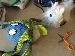
Friday, I went to Target, looked around in their toy aisle for a suitable stuffed animal to disassemble. Then in their dog toy aisle. I figured the dog toys will have squeakers and my electronics can fit in that area (since, of course, I’d remove the squeaker). I came home with two items.

MaxAndDoggie

The octopus is a dog toy. The dog is a human toy. I’m sure this makes sense.

Surgery1Is it mean to make the other one watch? 

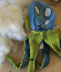
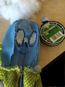
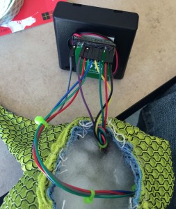
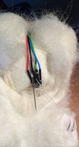
The next step was to remove the stuffing, remove the backing from the eyes so light can shine through, then affix the LED and accelerometer.

insideout

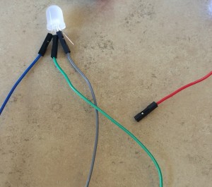
I’m a little worried about my LED.  Either I haven’t been consistent wiring up blue and green or they randomly change on a per-LED basis. (Ok, I am using two varieties of LED so it may be that.) That is wired according to the datasheet. But then when I wire the board, I end up needing to swap the blue and green. Sometimes.

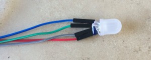
Anyway… that is just to show the wires. The next step is to clip each one (leaving the others with their colors so as not to get confuse). The goal is to clip as short as possible but no shorter. So aim for three snips per since too-short is bad but too long isn’t.

clipLEDLeads

Then hotglue it all together. (CUE: Foreshadowing music.)

hotglueLED

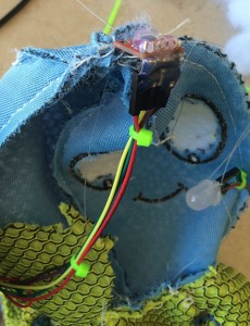
I attached the LED with fishing line, trying to keep it centered on the face but a little free floating.

affixingTheLED

The fishing line is coiled around the LED, maybe a dot of hotglue, then tied at the head, and threaded through at the bottom. With some force, the LED can be shifted up and down but it stays where I leave it. I want the LED to stay where I put it but also float in the stuffing.

puttingOnTheAccelerometer

Next goal: when you pat the head of the octopus and the accel fires. Happily, the accel has two mounting holes. I used those and more fishing wire through the seams of the head. I also, characteristically, hotglued the metal bits and the cables on to the connector. Think of hotglue as the pauper’s potting substance.

Intelligent people would test all the electronics at this point. You know, before adding stuffing. But, of course, do as I say, not as a I do.

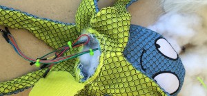
stuffingMax

Some stuffing, in the same role as screws in other projects, is expected to be leftover. They overdesign these things anyway.

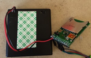
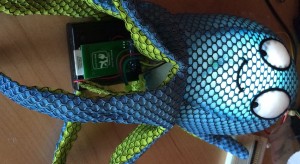
Now, add batteries! I need to have a way for the user (the elderly neighbor) to change the batteries. And I need to have a way for the caregiver to do the annoying-as-all-getup BlinkUp to send the WiFi SSID and password to the Imp card. And yet we also need to have it all look nice and stay in place.

doublestickTapeAndImp

My only advice is to try it out a few times before making any decisions. There were many ways for it not to work and only one or two that it was possible. Double backed tape (the slightly foam-like stuff) is very useful, for those spots where hotglue isn’t.

finalBitsOfHotGlue

Finish the wiring, add hotglue, stick to the double back tape. Stand on battery box on end to show off hotglue, not realizing the sense of vertigo that might lead to.

Really, you have to test him before buttoning him up. Really, really.

glowingWithGuts2


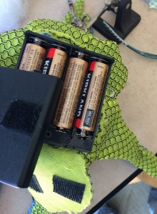
Now, add some velcro to the battery compartment. Then to the flap of fabric on the bottom.

velcroBatteries

Shove it all into the plush body. Nicely of course. Possibly adding a bit more of that stuffing so there aren’t any lumps due to the electronics.

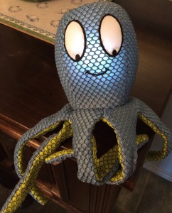
Put him somewhere that you walk by often. Pat him. Mine is a little slow to light but it is such a happy light that it is worth the wait.

maxwellHappyToMeetYou

Ok.

Now, this all looks pretty good, if I do say so myself.

But you maybe are thinking “well, these are instructions from an expert” but here’s the thing: This is the first time I’ve ever modified a plushie to take electronics.

Sure, I worked at Leapfrog, but they had real fabricators (they had the first 3d printer I ever heard of!). So. If you are thinking this is too hard, go out and buy a $5 dog toy and try it. I was pretty shocked at how not-hard it was.

Or you can do a $4 person toy.

doggieHeartLED

You didn’t think the dog was going to escape unmodified, did you?

This is plain thread, sewing the LED into the inner lining of the plush body (don’t want to see the stitches on the outside). I decided the doggie’s heart should light up. And I’m going to have to use 3 AAs or 4 AAAs to fit into the diminutive body, so it will need its batteries changed more ofent.

Of course, I just put my last accel (and Imp) into Maxwell so it will be a little bit before the fuzzie dog gets the rest of its gear. I should go push the buy button on Sparkfun. I am excited about the high potential for cuteness from the fuzzmonster.

Even without the hardware, now I can continue the tutorial. (Or go outside and play before the heatwave next week.)


h1

An LED in every plushie

April 10, 2014

Happily, one of my co-conspirators in the are-you-ok widget knows how to sew which means that we can progress to the next steps of development: productization.

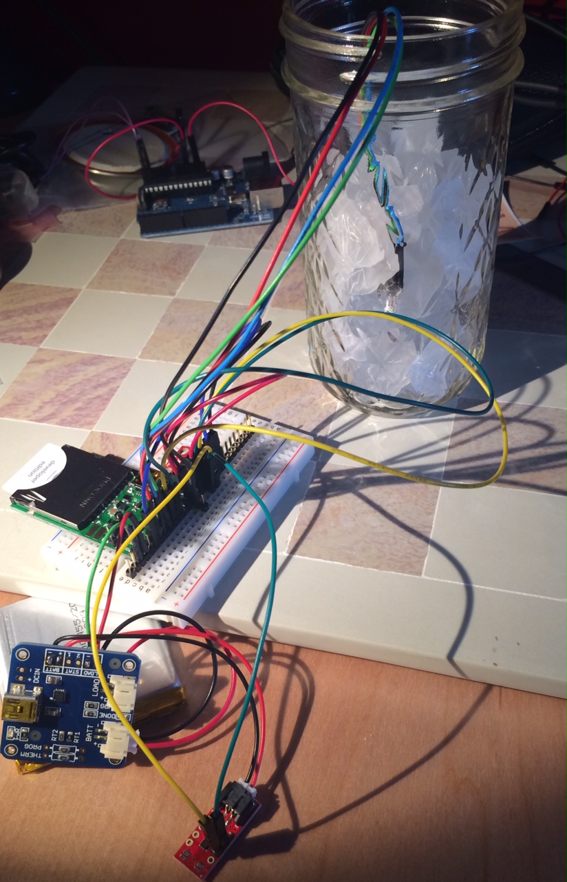
Here is what it looks like now.

naked gadgets

That is distinctly not cute. The jar of frosted glass is to hide the LED, so it doesn’t shine brightly in my eyes, the glass diffuses the LED. This is not a long term solution.

Right now the LED color is related to whatever the acceleration is: if the board is in the shown configuration, then the LED shines blue. If I tweak it to be on one edge or the other, it shines red or green. I enjoyed playing with the accelerometer to color translation but it was always just a diversion, to make sure I could see what I was doing.

So, why is the device going to have an LED? It is important for the user to know the unit received their attention. But I also need to show errors: low battery and no WiFi connection. With an RGB LED, my plan was:

  • GREEN or WHITE = acknowledge
  • YELLOW = low battery
  • RED = no WiFi

But now that we are talking about building the plushie, there were many good questions about the LED.

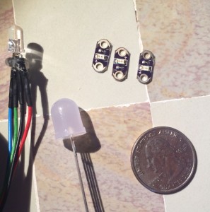
Three LED options

I am currently using a simple, standard RGB LED. If we use it, we’ll have to put it behind something (i.e. fabric that passes the light or milk jug material to diffuse the glow).

There is another option. I have small LEDs that are intended to be sewn into a device, to be shown. We could make them into coat buttons (one green, one yellow, one read).

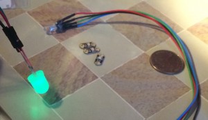
When purchasing for this widget, I got a larger (no more powerful, just physically larger) LED with built in diffuser. This lets the light be a nose or center of a bowtie, something external to the device. I finally connected it today, it looks really nice (taking a picture of a lit LED is not a good way to see it, let’s just say that diffuser creates a gentle glow).

Gentle green glow

The LED will be on a long set of wires, 5-12″ depending on what is needed. The wire leads (shown in the glowy picture) will be clipped so there is little or no metal showing but there will be about an inch of rigidity after the LED.

Either of the two RGB LEDs can be hot glued to fabric or their wires can be sewn into the fabric. Either way will secure them. The single-color LEDs have those easy-sew holes.

The accelerometer will also be on a five-wire cable. It can be placed away from the rest of the electronics and the battery. This will let it be in the hand if we want the user to shake hands to wake up the widget. Or it could be on the head and the user can pat it. (And this is why an accelerometer is superior to a button. (I hope!))

The rest of the electronics (battery, charging board, electric imp board and the connections) should all be low in the creature, keeping its center of gravity low to allow for upright posture of the animal. Further, the back should velcro closed; we need to program the Imp for the WiFi of the house: we will need access to it.

Next, the system is battery powered (USB charging). The USB port (or cable) needs a way to be inserted, ideally without slipping out all of the other electronics guts.

A few more thoughts on making the plushie: child-safe material is critical, nothing flammable. I will make the electronics as safe as I can but having something like nylon which is both electrostatic and amazing flammable, well, I strongly prefer felt.

h1

In which our intrepid heroine learns about resistor dividers

September 5, 2013

I need to monitor my gadget’s battery.

It has a 4.2V LiPo battery with Adafruit’s USB charging circuit. The system can be charging and running at the same time. However, the circuit does not have a fuel gauge or other monitoring information. It has a couple LEDs to say when charging is finished and when it is charging, but nothing to say “battery is nearly dead” (what I need).

My Electric Imp can only take up to 3.3V as an input. If I try to plug by fully charged battery (4.2V) into my Imp’s ADC input, well, fire is fun but bad. (Ok, it probably won’t cause a fire but it may cause an early demise to my Imp.)

Level shifting a signal is a common thing to do. I know this because, in role as software engineer, I have said, “Can’t the hardware just level shift it to a better range for the software?” It is easy!

When someone else does it.

Swotting up

Faced with the problem, I went off to read a little bit. I asked my EE friends to recommend books (other than the physically heavy, mentally heavy, doesn’t-come-in-Kindle Art of Electronics). I read Make:Electronics awhile back and enjoyed it but it was too simple. I need something beyond “here’s how to read a schematic” and more on the order of “here’s how to solve the 25 most common problems a DIYer will have”. Though if they ever do a Headfirst Electrical Engineering book, I’d be all over that.

Anyway, I eventually found that I want a resistor divider. This is like page 3 of a good electronics book so it wasn’t like I spent more than an hour on it. I don’t remember which web page made me think, “This is what I need” since I found it in a few places, including Wikipedia. Here’s what I learned about a resistor divider:


So if Vin is my battery and Vout is going to go to the Imp’s ADC to be measured, I need to set the resistor values (Z1 and Z2) to be something that makes sense.

I’m too lazy to do real math when I’m just poking at this. Ideally, I’d look at the range I want to measure (4.2-2.8V) and the range I want it to shifted to (3.3-0V) and crank. But lazy. So let’s just set Z1=Z2 so my resistor divider divides everything in half. I can prototype that and not blow the Imp, work out the details later.

But wait! Resistors to ground are power vampires. Since this is a battery system, I want to minimize power.  I typed “power calculator” into Google and came up with a reasonable webpage that would do the math for me, though the equations were there so I went ahead and thought about it. Here is the important equation, from Wikipedia:

So if I want to minimize power… then I need to maximize resistance (R).

I know I’ve used these equations before but I’ve always been answering a review or exam question, not my own need-to-know musings.

Next, I thought about looking through my bag of resistors. But I realized that the 4.2V already gets translated to 3.3V so why didn’t I use that? I don’t even need to dig through a pile of anything.

Use existing resources

I connected 3.3V to my ADC input and wrote the software to sample the pin. Well, really I just copied it from the Electric Imp Sampler API page and then got it working for my system.

The ADC measured 0xFFFF (maximum value). That made sense, it can measure 0-3.3V and I was putting in 3.3V.  I sampled every second as my battery took forever to die, eventually it measured 0xFFEF. Since the ADC is only 12 bits (shifted over to 16), that actually means there was only one bit of difference.

One minute after it went from 0xFFFF to 0xFFEF, it died. So there is only one bit of difference between “great” and “dying”. Plus, only one minute of “dying”.

This method won’t work.

Resistor networks, Part 2

Well, I had estimated the resistor math so after my failure, I got my bag o’ resistors and fished out the highest value ones: 91MOhm, 33MOhm, 10MOhm, 1.5MOhm. I’ve got several of each, from buying a pack of 500 at RadioShack.

I was pulling over my solderless breadboard when I realized that this was too easy. I started hearing that “monsters ahead” music in my head. (Dear brain, can’t we find another way to communicate? And what does the Gilligan’s Island theme mean?)

Plus, it was about lunch so I shot off a quick email to Phil (of Weekend Engineering) and told him my plan. His reply was two paragraphs long. The first one made me wish we’d used a white board:

The voltage divider output is just R2 / (R2 + R1).  So if you want your peak 4.2V input to be 3.3V at the output, you want a ratio of 3.3 / 4.2 = R2 / (R2 + R1), so you want resistors proportional to R2 = 3.3, R1 = 0.9.  This makes sense intuitively if you think of a series stack of identical resistors with the voltage dropping across it.  If you had a stack of 100 equal 1 ohm resistors, then 1% of the voltage drops as you go through each resistor.  If you put 4.2V in the top, the voltage decreases by .042V every resistor you move down.  22 resistors down, the voltage has dropped by 22 x 0.042V = 0.924V to 3.276V.  So R1=22 ohms (the 22 one ohm resistors in series), and R2 = 78 ohms (the remaining 78 one ohm resistors in series.)  There’s your 0.9 : 3.3 ratio.

He probably did all that math. None of my “well, voltage squared is around ten” ballpark nonsense for him. So, cool, he did the math. I can just use his answer.

The second paragraph burst my bubble:

Now, the larger resistors you use, the less current you’re drawing through this stack of resistors.  BUT, if you draw current out of the stack, into your ADC, then the you change the voltage, because the resistor divider assumes that there are no other current paths.  So the max size resistor you can use depends upon the effective input impedance of your ADC.  You want that impedance to be very large (10X or more, possibly much more) compared to the total resistance of your resistor divider.  As the current through your resistor divider gets very small (because the resistors are huge), that signal will also be more and more subject to sources of noise. That’s the motivation for not maximizing.  (Otherwise, you’d want to just use giga-ohm scale resistances.)

Yeah… I think that was the monster: why doesn’t everyone use giant resistors? And how am I to wade through Electric Imps documentation to find what the input impedance is. (I like my Imp but their Wiki is often a maze of twisty little passages, all alike.)

I looked at their forums (mental note: write a blog post about why I deeply dislike forums) and found an answer deep in a comment thread: around 50kOhm. Later in the thread, they report which processor the Imp uses (but I don’t think they want to bandy that about so I’ll let you look). I went to the processor’s datasheet (already on my harddrive as I used it in a client project recently) and 50k looks right.

So according to Phil, my resistance needs to be 1/10 of the input impedance: around 5k. But the power dissipation is huge! (3.528mW, Phil and I exchanged emails and, again, he did the math.) Essentially, it burns 0.8mA all the time.

This is a crime in a battery powered system.

To deter my continued questions, Phil suggested using a FET to control whether the battery monitor was on. But that requires an IO pin. I don’t have any extra, I’ve already made my tricolor LED a bicolor LED since I need to have a pin from the accelerometer to wake up the Imp.

Stomp stomp grrr. Electrical engineering is all about making difficult things more difficult. Hmph.

Buy my way out

Once I got over my post-lunch-need-a-nap-fussiness, I thought about some projects I’ve worked on and tried to remember how the problem was solved (without cheating and looking at client schematics). I remember someone swearing at a fuel gauge driver and an EE remarking at how stupidly expensive the part was. A little bit of searching led me to a SparkFun board with an I2C power monitor.

The first product comment is a plea to add this to a USB LiPo charger board. That was two years ago. Nothing. Not on AdaFruit or MakerShed either. Someone is missing a big opportunity here.

Anyway, this bumps my materials cost up by $10 but solves the problem very neatly. Plus, since it is I2C, I actually get an IO pin back so I can have a tricolor LED again.

Tempting, so tempting.

Plan

If this was a startup, I would be strongly in favor of buy instead of make. You can always make (and make cheaply) later but you can’t get the startup rolling if you take on too much at the start.

I think I’ll sleep on it and see if I can find a better solution. One that doesn’t involve much soldering.

Sadly, one of the negatives is that I need to buy a few other pieces of gear and right now I’ve got carts on SparkFun, AdaFruit, and Digikey but I don’t want to have three orders of stuff. I don’t know why. I’m just that way.


h1

A promise that, in the future, it will be better

September 4, 2013

Elizabeth came on my podcast to talk about Dolores, an older neighbor who lives alone. We got to talking about a device that would let Dolores maintain her independence while reassuring her family (and Elizabeth) that she is fine.

The idea is similar to the thinking-of-you jar I’ve been working on to explore the Electric Imp. Essentially, add an accelerometer, put it all into something cute (i.e. a teddy bear), have Dolores pat it when she wakes up (or if it is in the kitchen, when she walks by). If Dolores doesn’t pat it by 10am or three times a day or (setting to be determined), it will contact her family who can call and checkup on her.

This isn’t a hard concept. And I’ve been scooped a bit by Goodnight Lamp. (Hmph! People who take my ideas and go back in time to make them!) But their solution is pretty expensive (~$150) and I think I can do something for $80 from off the shelf parts.

Parts:

On the podcast, I said I thought it would cost around $80 to do a handcrafted one and my total here is $81. Yay estimating skills! Oh, I forgot:

  • Adorable receptacle: priceless.

On the show we also talked about features:

  1. Dolores would pat the bear.
  2. WiFi or other configuration to be set up by a daughter, Elizabeth, or other caregiver.
  3. Bear will also light when people hit a website (so the thinking of you functionality).
  4. System will message daughter (text, email, phone) if Dolores doesn’t pat the bear before certain times. (No check-in)
  5. System will also message daughter if bear is not charged or service is down for some reason.
  6. Daughter can see when the bear was patted (to verify system is working).
  7. Chargeable: 1 week of battery. Plugged in via USB wall wart.
  8. If battery is low (1/3 usable charge remaining or 3 days), system will email Dolores.
  9. If the battery is very low (2 or 1 day of battery left), system will email daughter.

Some I added later:

  • The bear will respond to a pat with an LED light (white if tricolor, green if red-green).
  • If the bear’s charge is low, it will respond to a pat with a blinking red light.
  • If you keep patting, the bear’s LED turns yellow. After thirty seconds of intense “patting”, the bear turns red and messages the family.

None of this is all that difficult. I looked at the Electric Imp hardware. I need to add battery monitoring so I’ll learn their Sampler class. And I need to add an I2C accelerometer but I already made an I2C LED work so I do not expect a problem. Much of this is server side, the agent software that I’ve been avoiding. I know in theory how to do it but I suspect the practice will be like hitting my head on a wall a few times.

Some of the work will be electronics: the battery is usable from 2.8V to 4.2V, the ADC input to the Imp presumably can’t go above it’s operating voltage (3.3V) so either I need to sort out a level shift (resistor divider? but that is a waste of power!) or figure out where else I can monitor power (maybe going into the Imp, on the April board?).

Also, I know an accelerometer is overkill, especially three axis ones; there are other motion sensors. On the other hand, I know how to use an accelerometer really well and I’ve got many lying around. Though I wonder… a temperature sensor would cost nothing but it takes longer to work and breaks my patting method.

Also, since the unit is going to be sleeping most of the time (for power reasons), the pat needs to wake it up. The Electric Imp has six pins available. I’m using 2 for I2C to the accelerometer, 1 for monitoring battery voltage, and 3 for the tricolor LED. If I need the accelerometer to interrupt the processor, I’m going to need to go to a bicolor LED so the user will only see red, green, and yellow. I think that is ok. But it makes me wonder if the accel really is the way to go. I don’t think I want a simple push button switch (not cute). Well, I need to go look at force sensitive resistors and soft potentiometers. Though how those are going to wake up the processor, I don’t know.

Yet.