Posts Tagged ‘learning’

h1

Releasing boards

March 17, 2014

The next few weeks are free of paying work (I do hope it is only the next few weeks but I am really glad to have a few weeks off).

I’m finally getting back to my own projects. The are-you-ok widget is probably the big one but before I get back to there, I’m releasing boards for my own project. Oh, some back story first:

I want a little motor board.

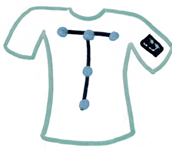
Actually, stepping further back… I want to build a tshirt that will help with my posture while sitting at a computer. The prototype is a T across the back, ending on each shoulder. There are three points along the top and three down the middle (with one share so there are five points). Each point has an accelerometer and a motor and connectors.Posture Shirt Sketch


I want to pass PWR, GND, SDA, SCL to all five sensors somewhat using the motor boards as a way to conduct and split the signal. Also on the motor board is, well, a motor: a  small coin cell sized motor.

I want to turn the motor on via GPIO which doesn’t have enough current to direct drive the motor so I need a MOSFET.  [Processors can’t drive motors directly because they don’t have enough oomph. The processor connects to the MOSFET which acts like a switch. Then the processor says “on”, the MOSFET turns the motor on, sourcing the power from another line (the voltage from the battery).]

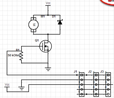
Here is the schematic, using Digikey’s SchemeIt. Unfortunately, SchemeIt is not something I can use to send to a board (PCB) fabrication house. [That would be like drawing the outside of a house in detail but leaving the inside as an exercise to the builder.]

Motor Circuit Capture

I have three connectors on the schematic, if the board is square, then these are on the East, West, and South sides. You can see the connection pass through to each connector.

I’ve wanted these boards for a long time, ever since I tried to make this (pretty simple) circuit myself. I’m not a good technician. I don’t have great soldering skills. What is worse, if it doesn’t involve a processor, I’m not very good at debugging hardware. So that was a swing and a miss. 

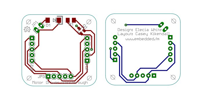
However, I have this podcast so I whined about it on the podcast. Well, actually, I wanted to know which electrical CAD software I should try (one that isn’t many thousands per seat). The answer is KiCAD but a listener said he could layout the board for me. And Casey did.

Motor Board Layers

He finished in early December. And here we are in mid March. I am so embarrassed by the delay. One thing just led to another: new and difficult contract, the holidays, vacation, cold, working hard to make up for missed time, the embedded system conference deadlines. And with many such projects, once I got a couple weeks behind, instead of rising to the top, it just got buried.

However, getting buried is no excuse. I’m returning to dust it off and finish it. Having worked now with higher power motors (and with FETs and how to blow them up), I’m a little more confident in my circuit.

Now it is time for a few of the difficult parts. I have released boards to fab and kitted parts but that was a long time ago. I’m really nervous but I don’t have a good reason for it. This isn’t going to cost thousands of dollars, it is pretty cheap overall. I suspect the nerves are from it being a new thing and I’m doing it more in public so failure casts a wider shadow. I suppose “suck it up” is the only right answer to those feelings.

Things to do:

  • Put it on github. This is an open source project, always was intended to be.
  • Go to OSHPark to get boards fabricated, release the design files to them (the gerbers).
  • Order parts from Digikey.

My goal is to get those done today. Then I’ll wait a couple weeks and put it all together. I’d better get to work.


h1

Where to start?

October 16, 2013

I got a message from someone who read my book. He said he enjoyed it (yay!) but  was disappointed it was mostly theoretical (boo!), and didn’t recommend a specific chip and give some tutorials on how to start using it. He asked if a $500 class would be a good way to get started. His background is software (I’d suggest different things for a hardware engineer but that’s a different post).

This seemed like a neat question so I answered and I figured I’d tell you my answer too, with a few only a few mods:

The chips change so fast that a book would be out of date before it was published. The class might be a good way to get started though, really, I’d say spend $50 on an Arduino board and build yourself a fancy Christmas light (or, if you’ve got time now, a Halloween scar-ifier of some ilk).

Arduinos have Atmel chips, usually the Atmega, a line of chips that is used in many shipping products. The community is huge so you won’t be learning alone. And the accessories for ti are amazing. You can start out in their C++ environment but strip it down to a microprocessor system and your own drivers if/when you are ready.

Another good source of software-to-embedded boards are the ones from mbed.org. They cost a little more but do some of the underlying drivers for you (and don’t make you fuss with cross compilers). They have more processing power (a lot more) so you’d get to see the ARM Cortex-M0 and Cortex-M3 which are the hot processors in the 32-bit space.

Maybe look at Electric Imp. They’ve got a neat system that lets you hook wifi and cloud services to lots of things. They do some embedded and it isn’t necessarily something you could build a career on but to stick your toe in, well, hooking your oven to the internet has never been easier. 🙂

Finally, lots of people love Raspberry Pi (and Beagle Bone Black). I see those more as Linux computers with a few limitations than proper embedded platforms. But maybe that is a good way to transition.

Circuit Cellar Ink is a good magazine. So is MAKE. They both will let you see what processors people are talking about and using in hobby stuff. Or look on the adafruit.com, makershed.com or sparkfun.com tutorials pages.

For more professional development (less hobby fun), contact TI, ST, Atmel or NXP and ask when they’ll have training in your area. Many times the training is free (and they give out dev kits!)… essentially you are letting them brainwash you to use their parts. But they all have good processors so no harm done. The embedded systems conference (DesignWest) isn’t until March 2014 but that is a good place to see all the vendors in one place (San Jose, CA).

Does that give you enough places to start?

I have a podcast (http://embedded.fm/), some of the shows cover how to get started with one thing or another though, again, those are starting points, not in-depth discussions.

Let me know how you get on.

And if you, dear reader of my blog, use any of this advice or want to suggest other things, please let me know.


h1

MOSFETs, games, and a demonstration of shiny object syndrome

September 9, 2013

Conversation this morning:

Me: You named one of your gadgets MOSFET... 
Him: Yes...
Me: Why? Is it something to do with Star Wars? Boba Fett?
Him: (Uncomfortable silence.) No. They are used in music amplifiers.

I keep coming back to MOSFETs. I keep seeing them in different contexts where they end up being the “oh you just put a MOSFET in there and it will work the way you want” component.

Maybe it is time I learned what this magical component does.

As a pretest, though, I’ll splat out everything I can think of.

  • When I wanted to connect a IO to a motor, the IO pin didn’t have enough current. So the EE (Phil) put in a MOSFET so I could toggle the IO line to get the motor to turn on and off without pulling current through the processor.
  • When I asked Phil about my resistor divider sucking too much power, he said I should put in  a MOSFET so the divider was only on when I needed to measure the battery. I didn’t carefully read the ensuing EEspeak because I don’t have an extra IO pin.
  • A FET is a form of MOSFET. Probably one with less moss… Actually, it is probably that a MOSFET is a form of FET. Probably with more moss. Really though, there is probably no moss, it tends to be damp and that’s bad for electronics.
  • It seems to be a switch that is controlled electronically.
  • They come in n and p varieties. I don’t know the difference.
  • (And this just in!) They are used in musical amplifiers.

So, let’s be clear: I’ve used MOSFETs before. But as I try to design my own hardware, I keep getting smacked upside the head with them, like getting hit with a fish tail as the fish escapes the boat and swims away. That’s always been ok with me: I never really wanted the fish. But now I want to understand MOSFETs. And not just for a few minutes until some shiny other thought comes along.

Let’s go back to what Phil said in my resistor divider email exchange.

To prevent that leakage current you could just put a FET to turn off that voltage divider when you’re not checking the battery voltage. You could use a high-side P-Channel FET, (between VBat and R1) but turning it off solidly would require a voltage equal to (or higher than) the battery, or you could use a low-side N-Channel FET, but then you’d still have the leakage current through the ADC.  Although that 50KOhm is probably only while it is sampling, not when it is not in use.  So that is what I would try for a minimal-part, minimal cost solution, if you have a spare digital I/O to turn that FET on and off…

Ok. Well, I guess I retained enough of that though I suspect Phil copied the paragraph from the last five times I asked him something that required a MOSFET. I suppose what I need to do is use MOSFET in a circuit I design myself.

First, a little more information, courtesy of Wikipedia. Wow, that article is long. Let’s just come back to it, ok?

And since my attention span is tiny this morning, let me tell you about this game I’ve been playing. It is Circuit Coder for the ipad. It gives me little challenges, like build a NAND gate using only NOR gates, then I build what it wants, trying to think through the problem. Here is my half-adder.
Circuit Coder Half Adder solution

I had a decent amount of logic in college, in the CS courses, so this NAND and NOR gates are buried deep in my brain but have a solid foundation. I like the puzzle aspect. I’m a little stuck on SR latches but I have a plan to go read about them and I suspect they’ll fall pretty quickly.

Since some of the puzzles are tricky, there is a walkthrough. I was afraid to look at it for fear of taking away the puzzle aspect. However, the walkthrough is only for the first 3.5 minutes of the game so I am more likely to cheat using a computer engineering text book. And a game that can get me to look up how components work and demonstrate logic gates so effectively… this is more what I want from learning. Sneaky learning. Though, I wish the game had a little more help and could be a little more competitive (what is the minimum component solution for each?). But completing puzzles is very satisfactory.

I was hoping one of the components I need to make is a MOSFET. But looking around now, I don’t see that in Circuit Coder. (Though I do see a review that rates this game highly and suggests Codea as a good learn-to-code game. Whew, expensive though! And then my appolearning “trial” expired and I am considering whether to buy their (too expensive) app so I could learn about other instructional apps.)

And this is why my quest for MOSFET intuition has, to date, been for naught. I keep looking at the Wikipedia article and then finding something else to do. It is too theoretical and not tactical enough: what should I use a MOSFET for and why?

Getting away from the shiny distractions available in Wiki, I switched to looking at Charles Platt’s Encyclopedia of Components in Safari. (If you write an O’Reilly book, you get a free lifetime subscription to Safari online. Happy perk!)

There was nothing about MOSFETs in the table of contents. That seemed so unlikely for a book titled thusly. I searched for MOSFET, found some entries under Chapter 29. field effect transistor.

I bet “field effect transistor” has been used to sound very sci-fi. If I had a band (made up entirely of light theramin), it would be called “field effect transistor”.

And apparently, I should read chapters 26-28 before proceeding so I understand diodes and transistors because those are related.

I had hoped to share my new-found understanding with you in this post. Instead, I feel like I’ve wandered around in circles until exhausted. I’m going to go sit in a corner with this book and see what I can learn.

Or maybe I’ll do some paying work.

Naw, I think I’ll go run errands.

Or maybe push reload on twitter.


h1

In which our intrepid heroine learns about resistor dividers

September 5, 2013

I need to monitor my gadget’s battery.

It has a 4.2V LiPo battery with Adafruit’s USB charging circuit. The system can be charging and running at the same time. However, the circuit does not have a fuel gauge or other monitoring information. It has a couple LEDs to say when charging is finished and when it is charging, but nothing to say “battery is nearly dead” (what I need).

My Electric Imp can only take up to 3.3V as an input. If I try to plug by fully charged battery (4.2V) into my Imp’s ADC input, well, fire is fun but bad. (Ok, it probably won’t cause a fire but it may cause an early demise to my Imp.)

Level shifting a signal is a common thing to do. I know this because, in role as software engineer, I have said, “Can’t the hardware just level shift it to a better range for the software?” It is easy!

When someone else does it.

Swotting up

Faced with the problem, I went off to read a little bit. I asked my EE friends to recommend books (other than the physically heavy, mentally heavy, doesn’t-come-in-Kindle Art of Electronics). I read Make:Electronics awhile back and enjoyed it but it was too simple. I need something beyond “here’s how to read a schematic” and more on the order of “here’s how to solve the 25 most common problems a DIYer will have”. Though if they ever do a Headfirst Electrical Engineering book, I’d be all over that.

Anyway, I eventually found that I want a resistor divider. This is like page 3 of a good electronics book so it wasn’t like I spent more than an hour on it. I don’t remember which web page made me think, “This is what I need” since I found it in a few places, including Wikipedia. Here’s what I learned about a resistor divider:


So if Vin is my battery and Vout is going to go to the Imp’s ADC to be measured, I need to set the resistor values (Z1 and Z2) to be something that makes sense.

I’m too lazy to do real math when I’m just poking at this. Ideally, I’d look at the range I want to measure (4.2-2.8V) and the range I want it to shifted to (3.3-0V) and crank. But lazy. So let’s just set Z1=Z2 so my resistor divider divides everything in half. I can prototype that and not blow the Imp, work out the details later.

But wait! Resistors to ground are power vampires. Since this is a battery system, I want to minimize power.  I typed “power calculator” into Google and came up with a reasonable webpage that would do the math for me, though the equations were there so I went ahead and thought about it. Here is the important equation, from Wikipedia:

So if I want to minimize power… then I need to maximize resistance (R).

I know I’ve used these equations before but I’ve always been answering a review or exam question, not my own need-to-know musings.

Next, I thought about looking through my bag of resistors. But I realized that the 4.2V already gets translated to 3.3V so why didn’t I use that? I don’t even need to dig through a pile of anything.

Use existing resources

I connected 3.3V to my ADC input and wrote the software to sample the pin. Well, really I just copied it from the Electric Imp Sampler API page and then got it working for my system.

The ADC measured 0xFFFF (maximum value). That made sense, it can measure 0-3.3V and I was putting in 3.3V.  I sampled every second as my battery took forever to die, eventually it measured 0xFFEF. Since the ADC is only 12 bits (shifted over to 16), that actually means there was only one bit of difference.

One minute after it went from 0xFFFF to 0xFFEF, it died. So there is only one bit of difference between “great” and “dying”. Plus, only one minute of “dying”.

This method won’t work.

Resistor networks, Part 2

Well, I had estimated the resistor math so after my failure, I got my bag o’ resistors and fished out the highest value ones: 91MOhm, 33MOhm, 10MOhm, 1.5MOhm. I’ve got several of each, from buying a pack of 500 at RadioShack.

I was pulling over my solderless breadboard when I realized that this was too easy. I started hearing that “monsters ahead” music in my head. (Dear brain, can’t we find another way to communicate? And what does the Gilligan’s Island theme mean?)

Plus, it was about lunch so I shot off a quick email to Phil (of Weekend Engineering) and told him my plan. His reply was two paragraphs long. The first one made me wish we’d used a white board:

The voltage divider output is just R2 / (R2 + R1).  So if you want your peak 4.2V input to be 3.3V at the output, you want a ratio of 3.3 / 4.2 = R2 / (R2 + R1), so you want resistors proportional to R2 = 3.3, R1 = 0.9.  This makes sense intuitively if you think of a series stack of identical resistors with the voltage dropping across it.  If you had a stack of 100 equal 1 ohm resistors, then 1% of the voltage drops as you go through each resistor.  If you put 4.2V in the top, the voltage decreases by .042V every resistor you move down.  22 resistors down, the voltage has dropped by 22 x 0.042V = 0.924V to 3.276V.  So R1=22 ohms (the 22 one ohm resistors in series), and R2 = 78 ohms (the remaining 78 one ohm resistors in series.)  There’s your 0.9 : 3.3 ratio.

He probably did all that math. None of my “well, voltage squared is around ten” ballpark nonsense for him. So, cool, he did the math. I can just use his answer.

The second paragraph burst my bubble:

Now, the larger resistors you use, the less current you’re drawing through this stack of resistors.  BUT, if you draw current out of the stack, into your ADC, then the you change the voltage, because the resistor divider assumes that there are no other current paths.  So the max size resistor you can use depends upon the effective input impedance of your ADC.  You want that impedance to be very large (10X or more, possibly much more) compared to the total resistance of your resistor divider.  As the current through your resistor divider gets very small (because the resistors are huge), that signal will also be more and more subject to sources of noise. That’s the motivation for not maximizing.  (Otherwise, you’d want to just use giga-ohm scale resistances.)

Yeah… I think that was the monster: why doesn’t everyone use giant resistors? And how am I to wade through Electric Imps documentation to find what the input impedance is. (I like my Imp but their Wiki is often a maze of twisty little passages, all alike.)

I looked at their forums (mental note: write a blog post about why I deeply dislike forums) and found an answer deep in a comment thread: around 50kOhm. Later in the thread, they report which processor the Imp uses (but I don’t think they want to bandy that about so I’ll let you look). I went to the processor’s datasheet (already on my harddrive as I used it in a client project recently) and 50k looks right.

So according to Phil, my resistance needs to be 1/10 of the input impedance: around 5k. But the power dissipation is huge! (3.528mW, Phil and I exchanged emails and, again, he did the math.) Essentially, it burns 0.8mA all the time.

This is a crime in a battery powered system.

To deter my continued questions, Phil suggested using a FET to control whether the battery monitor was on. But that requires an IO pin. I don’t have any extra, I’ve already made my tricolor LED a bicolor LED since I need to have a pin from the accelerometer to wake up the Imp.

Stomp stomp grrr. Electrical engineering is all about making difficult things more difficult. Hmph.

Buy my way out

Once I got over my post-lunch-need-a-nap-fussiness, I thought about some projects I’ve worked on and tried to remember how the problem was solved (without cheating and looking at client schematics). I remember someone swearing at a fuel gauge driver and an EE remarking at how stupidly expensive the part was. A little bit of searching led me to a SparkFun board with an I2C power monitor.

The first product comment is a plea to add this to a USB LiPo charger board. That was two years ago. Nothing. Not on AdaFruit or MakerShed either. Someone is missing a big opportunity here.

Anyway, this bumps my materials cost up by $10 but solves the problem very neatly. Plus, since it is I2C, I actually get an IO pin back so I can have a tricolor LED again.

Tempting, so tempting.

Plan

If this was a startup, I would be strongly in favor of buy instead of make. You can always make (and make cheaply) later but you can’t get the startup rolling if you take on too much at the start.

I think I’ll sleep on it and see if I can find a better solution. One that doesn’t involve much soldering.

Sadly, one of the negatives is that I need to buy a few other pieces of gear and right now I’ve got carts on SparkFun, AdaFruit, and Digikey but I don’t want to have three orders of stuff. I don’t know why. I’m just that way.
 

h1

All that I need now is a jar

August 20, 2013

One thing that I didn’t really get before working on my thinking-of-you webpage: all web developers write OpenSource code. Once it is on the web, anyone can read it.

Copyrights are fine but is copying someone else’s method of selecting colors of setting up a form or changing font colors for a section instead of a div really protected? I’m not talking wholesale page stealing, just copying snippets.

I didn’t do anything that I didn’t attribute (or learn from HTML and CSS book I mentioned before). But I did read a few random pages, trying to see how they did this or that. That was kinda neat, looking at how pages are put together, now that I speak a little bit of the language. I understand why so many things are hidden in PHP layers: so no one can see a site’s undergarments.

Usually, my code is seen by one or two other people, during code reviews or when it is reused, not by anyone who cares to look. I don’t think I mind but it is a little odd. I mean, what if there was a better way to do it? On the other hand, I’m such a noob at web dev that I’m sure there is. And if you tell me, I’ll be happy to know. So why am I nervous?

Here it is:

Thinking Of You V1

https://logicalelegance.com/portfolio/thinking-of-you-wout-id.html

That won’t actually blink my LED. While it will let you set your name (and color if you don’t like the one it chooses), it will give you an error when you try to send some love to Christopher. (Hey, if I’m going to be working on this, might as well make it my sweetie.)

The response page is ugly, I’m going to ask Electric Imp about making the response prettier. I don’t care too much about the no-id get-error version but the one with the real key just sends back a page with OK in it sans prettifying.

Note that I met most of my goals: it is one page, settings are hidden after you put your name in, the cookie works (though Firebug can’t find it which is a pain for debugging). I also added my stretch feature of changing the button text on reload. That was easier than I expected and it amuses me.

I updated the Electric Imp code so with the right key in the html, I can change the LED. But I’ve decided to use a PWM LED instead of my fancy I2C LED. That shouldn’t take too long (Electric Imp has RGB LED example code). Then I’ll combine it my USB chargeable LiPo, then put it all in a jar with some hotglue.