Posts Tagged ‘wordy’

h1

Another Day of Battery Life

December 16, 2014

To make a ring, I needed to minimize everything. Of course, if you’ve seen the picture, you already know I didn’t actually minimize much.

Still, batteries in wearables are a pain. For this wearable with my “you have to take it apart to charge it” methodology, well, longer battery life means this hack will exist longer. The more I take it apart, the more like it is that I’ll repurpose the parts to do something else. (I have this idea for a different ring…)

Minimizing power in Arduino is a topic that has been taken on by plenty of other people. And I happily reused their code and methods(Thank, you Nick Gammon!).

However, when planning a device, it is helpful to determine the size of battery you need. To that end, I made an Excel sheet (sorry, I default there) which I’ve put into a Google spreadsheet so you can see it with the math. The first sheet (words) describes the process in words. The second sheet (numbers) reflects the same information but with numbers. You fill in the orange boxes, it generates the green one.

The first step is to determine the different power states of the device. For Wordy, it is either on (display showing) or sleeping (Arduino asleep, accelerometer configured to wake and interrupt it).


My next step was to figure out how much time the system would spend in each of these states. My goal is for the ring to be on for about five seconds every five minutes. Sometimes it will be on more, as I play with it a lot. More often it will be sleeping, such as left on a table overnight. (Note: if you build a Wordy, I strongly recommend setting the ring so it will lose at Pong. Sometimes if you leave it on the X side with no Y tilt, the ring will play Pong by itself indefinitely.) Starting with the idea of five seconds per five minutes means I’ll probably be on the conservative side (unless it plays a Pong marathon without me).

Next, I measured how much current each state. I used my shiny new DVM-with-current-sensing (my old one didn’t have that (though it did have a more melodious beep in resistance mode)). You can use a resistor if you feel like doing it old school style.
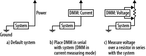
(This pic is from my book. If you were unaware I wrote a book, well, yes, I did and it is full of jokes. And dinosaurs. But mostly embedded systems.)

Finally, I calculated how long the device would last given a 40mAh battery (the largest I was willing to use due to size constraints). The result turned out to be much greater than I expected.

This does not have to be the order of events: you might start with the idea of how long you want the device to last and choose the battery accordingly. Or you may have a fixed battery and a predetermined life and need to determine how much time you can spend in each state. Happily, the math works in all the different ways.

Note that this value I got was greatly in excess of my self-imposed goal (which was a puny two hours). It is also greatly in excess of what I said in the build instructions (which was 48 hours). My wear-time was even greater than the estimated value: I charged on Tuesday afternoon and it died on Saturday night.

Though, I’m pretty sure I can do better than these power numbers.

When I measured the MicroView without the accelerometer, the on-state power fluctuated between 10mA and 14mA, depending on how much of the screen was lit. (All current measurements were taken around 3.7V.) If I modify numbers on the spreadsheet, the on-state power of 10mA to 14mA, it changes from 3.5 days to 3.1 days. I switched it back to 12mA as reasonable middle ground.

The accelerometer doesn’t add much to this on-state value. On the other hand, for the sleep-state power, it is a very different situation. The MicroView alone took 0.14mA. The MicroView and accelerometer together take 0.31mA. If I change the sleep-state power from 0.31mA to 0.14mA, the amount of battery life expected changes from 3.2 days to 4.9 days.

The accelerometer datasheet says the accelerometer’s current consumption is 6uA to 165uA. Looking at the numbers above (0.31mA-0.14mA = 0.17mA ~= 165uA), it is clear I should be able to reduce the sleep-state power by reading over the accelerometer datasheet again. (There is also an application note about wake/sleep features.)

Skimming through the app note, I don’t care too much about the precision of the data (though I might in Pong mode but that is an active mode so it is ok to use more power there). It would be no problem to turn the system from 14-bit mode to 8-bit mode.

Sleep mode is limited to 50Hz sampling but that is what I’m sampling at anyway. Why am I still seeing the max current?

Ahh, according to the oversampling chart, I may see 165uA due to high resolution sampling. I can go to 24uA with normal sampling or 14uA with low power. However, I want some filtering either through oversampling or via the low noise setting. The combination of low noise + low power is back to 24uA.

Making only one change (from high resolution to normal sampling) should be enough to increase my battery life from 3.3 days to 4.6 days. That’s exciting. Excuse me, I need to go see if that’ll work and what else I need to change.

[Note: this was crossposted from Wordy’s Hackaday page project log.]

h1

Hackaday: Wordy

December 9, 2014

I wanted to make build instructions for Wordy but since it uses both SparkFun and Adafruit parts, I couldn’t decide where. Though I did say I was going to put my next project up on Hackaday. I did that. There is a link to the code there as well as build instructions. Anyone here want to check it out for me? Maybe suggest what I forgot?

Wordy Ring

One thing already on my list is a project log of different ring making methods I tried. I’m going to do another pass with Sculpey, taking pics as I go. I also need a final picture of it all together, I plan to take that when I wear it out tonight.

h1

Giant rings are IN, right?

December 3, 2014

I finished up the working modes of my ring, so rev1 of the software is done. Here’s what it does:

On TAP: shows a vocabulary word. On tap or double tap, shows definition.

On DOUBLE TAP: starts Pong game, paddle position set by tilt of accelerometer.

On UPSIDE DOWN SHAKE: says to consider a question, waits for upside down shake (or punch) to give a response.

On PUNCH: puts up a punch word and a couple rectangles for emphasis.

As long as the wires are secure, this all works pretty well. I still need to format some of the Magic 8 ball style responses. And I could go through the vocabulary words to make shorter (better) definitions. I can probably pick up about 50 words too (yay!). I may continue to get rid of nonsensical floating point stuff so I can put more definitions in. Oh, and I should check the power usage, I didn’t minimize the accelerometer’s draw.

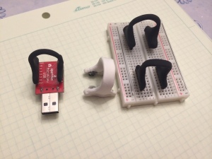
However, those tweaks can all wait as I need to make it wearable again. The button version was wearable but the ring blanks from that are a little too small for the accelerometer+battery stack up.

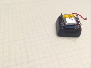
microView with accelerometer and battery

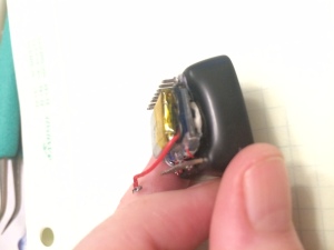
From another angle

MicroView, accelerometer and battery


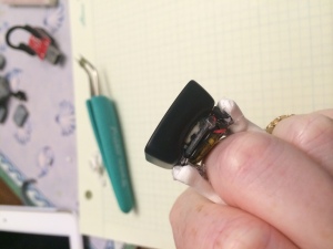
On the back of the MicroView is a dab of funtac (that stretchy sticky stuff you might have used to hang posters in your dorm room), a modified Adafruit 5V tolerant MMA8451 board (ahem, they didn’t need all that space for logos and mounting holes). Tiny wires are soldered to the board, then hot glued. On the other side, they are soldered to the MicroView.

On top of the accelerometer is a SparkFun 40mAh LiPo battery with its connector snipped. It is held on to the accelerometer with funtac (sometimes I build things entirely from funtac). I needed the battery on the outside so I can remove it for charging. The

This all stacks up higher than I wanted and doesn’t leave much space for attaching the ring to the device. With the button+battery version of the ring, I pressed the MicroView pins into the ring blank and press fit it all together. That doesn’t work so well now, especially as the poorly pressed fit doesn’t hold the power on.

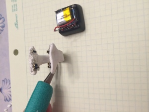
Add connectors


I snipped some jumper wire so I could build a connector on the inside of the ring blank. This was just a trial run. It worked out ok but I think I want to do something a little different for the real ones, maybe destroy 8 wires to get 16 connectors. Having attachments only on the pins of interest has some downsides (especially if I don’t line them up properly). More connector ends also lets me add some needed rigidity. Even these few fix the press fit problem. The female connectors are all too bulky though I may look around some more.

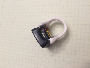
Ring on


It doesn’t look too bad. Though I think the new black version are going to be better (still waiting for those to dry).

photo 4

Well, let’s see it on!

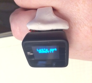
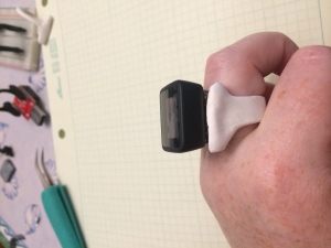
OnThe 5s timeout on the screen makes it impossible to get an in-focus shot by myself.  Ahh well, you get the idea. This angle is probably the nicest. From the side where you can see the stackup, not so nice. (Realistically, it wouldn’t be hard to cover this.)

head on

But I can’t leave it on that shot, one more, a little prettier.

Sideview

h1

Stuff I need

December 2, 2014

I know, I write this blog so people can read it. But then I hope only my husband reads it. Which he does but usually only after I’ve told him about whatever I wrote.

Anyway, I find myself going to the same pages a lot. I figure I can reduce my tabs by putting a few links here:

Yeah, I’m still working on my little ring. With a tap, it gives a word. Another tap, the definition. With a double tap, it starts pong (you tilt your hand to move the paddle). Another double tap (or win/lose), pong ends.

Today I hope to use the motion thresholds on the MMA8451 to detect when you turn your hand upside-down and shake (ahem, ask me a question!). I’ve already got the answer strings in there and I’m using 27166 bytes, out of 32k. Though I’m down to 100 words (instead of the 200 I started with).

Better get to work now that I can close some of these tabs.

h1

Air Punches!

November 26, 2014

My accelerometer FINALLY arrived (hint: don’t pay for expedited shipping until you know when their ship cutoff time is). It does not work. I am quite cranky about that.

This gets me to thinking about that fourth possible mode (three others flowcharted in previous post, flowchart is a verb, right?). I am pretty certain I can set thresholds to get an interrupt on a sudden motion, such as the very end of a punch (even an air punch). So… the ring is going to say “KER POW”, “BIFF”, and “THWACK” when that happen.

This amuses me very much. I thought it might amuse you. I plan to make it little screens with edges, Batman style, not just words. I suppose I have time to do that artwork and put it in the code. Since my accelerometer is DOA. Hmph!