Posts Tagged ‘ayok’

h1

Manatee photos

April 23, 2014

I usually say that if I am not blogging about my personal projects, I’m not working on them. That isn’t true this week.

I’m afraid that if I take the time to write everything that is bursting in my head, I won’t get to continue working. So I’m going to just put up some photos. These aren’t build instructions, maybe they are just place holders for all the stuff that should (and some that shouldn’t) be in the ayok build notes.

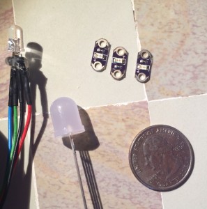
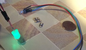
Choosing an LED has been tough. In that pic there are two RGB LEDs, both the same power but the big one (10mm) has a diffuser. The three little ones are red, yellow, green individual LEDs. They are from LilyPad which means they are built to be sewn into things.

Elizabeth made a manatee prototype, including the diffuse LED as a nose and the smaller three as buttons.

For the nose, the question of how to attach it to the fabric came up. Hot glue seems to be my solution for everything but that does make fabric feel yucky so I cut out a perfboard. Elizabeth then used the holes in that to build a prototype nose.

But before I show you how she put it together, here is the base-model manatee. The pattern came from cationdesigns.

It sits up unaided (thanks to some sand weights in the tail and lower belly). It is soft and utterly adorable.

But less so when you add an LED schnoze. That manatee body doesn’t have any stuffing but, even so, not the look we were going for.

The button style LEDs are kind of boring. And since they don’t color mix we lose a lot of flexibility. (All GPIOs are the Electric Imp are used!)

Using conductive thread seemed neat but the interface between pins and wires is not easy. To get the LEDs to light, I ended up knotting all the plus and all the minus sides.

Of course, the thing the thread likes to do most is make knots so that part was easy. I wasn’t thrilled by the look or the electronics side of those buttons.

Putting the tummy in the empty cavity of the body looked nice but that isn’t exactly realistic, the LED can’t just float around in open (deflated) air.

Elizabeth suggested that since we are using a double layer fabric, we could put it between layers . So I unraveled some of her work and shoved it in a newly opened seam in the back.

With the LED in between the two layers of fabric, t gave a nice glow. We are going to try that some more, to give it a tummy glow. I hope that works. It is better than our fallback plan of making the big diffuse LED into some sort of tophat.

The new manatee model also came with a pocket for electronics so we could make things fit. But before we see that, let’s look at the electronics build.

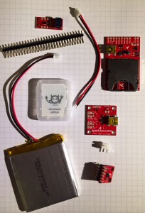
First a parts list in graphic form. This is also in a SparkFun wishlist.

Next I tried to show how things would get assembled. I don’t think I want to do a step by step assembly. The soldering isn’t too tough… But here is what I took while I built it.

First attach headers!

Next, attach red to ground and black to power. Sigh, that is really what happened in the next pic.

I figured it out two days later when the fuel gauge would not work, not even after I fixed its I2C lines. So, maybe this pic won’t go into the instructions.

I need an extra set of I2C pins and another ground pin. I devised this stupidly complex way to go about it involving another breadboard.

I’m not sure how to explain that you can follow this tutorial even if you solder like a drunken sailor. In high winds. Also, you don’t have to do this because you don’t need all these pins that I thought you might want.

Happily at this point we can go back to the manateee. Which I’ve named Hugh. At least this one is.

He’s got a pocket in his butt. This is what needs to fit.


From another angle…

I have more electronics than will fix, though it isn’t too far off. The problem comes from using up-down headers. With right angle headers, this would have worked better. So do I go back and re-do it with right angles?

Because while I jammed everything in there, it appears that Hugh has some unsightly wires coming from his, um, backside.


Ok, this one I took for twitter because I was getting Hugh’s Electric Imp to work. I found a short with the I2C connection (bad solder joint) and then the fuel gauge ground/power swap.


There are some software oddnesses with running two Impees from one account. It took me awhile to get it running. I’m still not sure how to differentiate between the two units (though I’m pretty sure there is a way).

Having gotten it working, I took some pictures today to help explain the wiring. The power subsystem could all be be stuck together: hot glue!

Actually, I wanted that foamy double stick tape but couldn’t find any. Note that only two sets of wires go out of the frame: I2C SDA (green) and SCL (yellow); power (red) and ground (black).

Those go to the Electric Imp board. Two bundles of wires then come off the Electric Imp board: the LED and the accelerometer. The LED has a red (Imp pin 2), green (Imp 5), and blue wire (Imp 7).

The LED pins are:

  • the longest is ground (black)
  • the short one next to that is red
  • the remaining inside one is green
  • the last one, outside, opposite red is blue

The accelerometer has power (red), SDA (green) , SCL (yellow), (nothing), Wakeup (violet), and ground. These all go back to the Imp board.

Finally, the un-taped, un-hotglued ball of wires on my desk.

So you can see, progress is being made.

The second set of electronics work. I have enough drawings and pictures to describe how to do the build (if not enough to do the stuffed animal). The code is working though I have some tweaks (multiple users need different names, handle email, and separate test from real code then comment it).

But Elizabeth is getting this set of electronics this weekend so expect another manatee soon (and maybe another set of electronics).

h1

In which it becomes obvious that I’m not in marketing

April 18, 2014

I want to name my are-you-ok gadget. I mean give it a proper name, something catchy and jingly. Something that takes the awkward description I give and then the example and turns it into a blindingly obvious system.

Unfortunately, I am not good at this. If it was up to me, all our pets would likely be called Bob. (It would make things easier, don’t you think?) Also, when working on a tshirt to improve posture, my favorite name (and the working name of the project before my husband explained the negative connotations): StraightT!

I thought to ask Elizabeth but she was the one who wanted to have it post to Facebook with a status of “Maybe not dead”. I find that hilarious but I’m not sure everyone would.

In the code, I call the thing ayok (for “are you ok?”). It is unwieldy to pronounce, I don’t say it very often. Even in my internal monologue.

A day or two ago, I had a brainstorm and decided that the name should be Mandy-the-manatee since the plush is (currently) a manatee. And Mandy is sort of a portmanteau of Maybe Not Dead (ok so Mande might be “better”).

I emailed Elizabeth to tell her the good news. I hadn’t considered it before but Elizabeth had this rant about how pre-named plushies are wrong. Wrong, I tell you. Owners should get to name their own animals.

Which, of course, means I immediately want to name mine Bob.

But back to a system name. How about POM for piece of mind? I bet the pomegranate people not appreciate it. Though their little heart logo would be nice too. As long as I’m going to infringe, might as well go all the way.

POL or Polly for proof-of-life? That’s another name for the animal, not for the system. Though Pet Polly isn’t bad and tells you what to do with the device.

What about GlaDos due to the “Still Alive” (also due to innate creepiness of having a stuffed animal spy on you)? I suppose that has a copyright or something.

Anyone want to suggest a name? The bar here is quite low.


h1

Fuel gauge for batteries

April 16, 2014

Lithium polymer (LiPo) batteries are strange beasts. I can’t simply measure the current voltage and tell you how full it is. (You can on throw-away AAs.) Worse, a nearly-full battery and a nearly-empty read about the same voltage until it become really empty and the battery dies.

Determining the LiPo battery’s state of charge requires an algorithm that monitors the battery over time and over a few charge cycles. The simplest way for me to do it for the are-you-ok widget is to buy the monitoring in the form of a small board: the LiPo Fuel Gauge.

However, while not adverse to reading datasheet, I just wanted to plug this board into my system and have it work. I did read the example code: it reads the percent from a register and sets up an alarm-interrupt I don’t care about.

I should have been more suspicious when my full battery read a state of charge (SOC) that was in the 30,000s but really, I didn’t care the actual number as long as I could see the power go down over several days. Except, with deep sleep working, the power is taking much longer than several days to go down. Last time I read the battery, it said 18664. Reading the voltage with a DVM showed it to be very high.

Then I broke that battery’s wire so I need to switch to another module (a very small one this time so I can check the fuel gauge better). Also, this time I’m going to read the datasheet, to get it set up properly.

I figured I might as well take notes here. Maybe note a few things about how to write instructions since that’s also on my mind. The intro starts off pretty good and a line caught my eye in the third paragraph.

A quick-start mode provides a good initial estimate of the battery’s SOC.

Good, that’s what I need. And I already know I can connect to it, at least to read registers. I can probably write registers but I don’t have that code for this chip.  (That’s like 3 minutes of coding and 4 minutes of testing so this isn’t a major deal.)

Next in the datasheet is a bunch self-congratulatory blahblahs that don’t help me solve my problem. Why do they do that? I already bought the thing, quit selling it to me and tell me the good stuff. I get through the “for the electric engineer” tables (those can be important to me but on first skimming, I tend to let the data slide over my brain), then  messy graphs followed by more coy hinting at their algorithm and finally to a section called IC Power-Up.

When the battery is first inserted into the system, there is no previous knowledge about the battery’s SOC.

Since the LiPo’s state of charge depends on it’s history, the first power up is tricky. It goes on to say about how the fancy-schmancy algorithm will converge with time. This was what I was depending on before (and about where I stopped reading the datasheet before). Eventually, the fuel gauge figures itself out, after a few charge and discharge cycles. Of course, if you are talking about months, then that isn’t so useful.

I want a way to charge the battery fully (because the charger says it is done and it have been charging for several hours) and then tell the fuel gauge it is full. Ideally, that will be covered in the Quick-Start section that is next.

A quick-start is initiated by a rising edge on the QSTRT pin, or through software by writing 4000h to the MODE register

Yay? Ok, so now I know how to go into quick start mode but what does that do? It doesn’t tell me. This is why I hate reading datasheets sometimes. It is like talking to a recalcitrant four-year old.

Moving on, maybe things will become clear if I keep reading. The next section is ALERT Interrupt. I don’t want that (not enough pins on the Electric Imp, maybe I could use pulldowns to double up the wakeup pin but that seems too much like work; I don’t mind polling the fuel gauge every hour since the unit needs to wake up and check-in to the server anyway).

The next section is on Sleep Mode. That should be interesting but since I can’t kill batteries, I haven’t done the last few power optimizations: put this and the accelerometer into sleep mode when they aren’t needed.

Let’s see, I can reset the fuel gauge, as though I power cycled it. Whee. (That was an unenthusiastic whee in case you couldn’t tell from the tone.)

Now for the Registers section. As a software person, this is the section I usually skip to. If this datasheet was a walnut, this would be the delicious meaty core.

Usually.

The SOC Register really should be giving me a percent full.

Units of % can be directly determined by observing only the high byte of the SOC register. The low byte provides additional resolution in units 1/256 %.

Ok! So my last reading was 18664, in hex that is 48 EB. Looking at only the high byte hex 48 equals decimal 72. My battery is 72% full. Look at that, it makes sense now.

On April 8th, my reading was 24839, in hex that is 61 07. So hex 61 is 97%.

Essentially I’ve been reading it wrong. To be fair to my previous self, I did look at the figure that showed how to read it which says something different than the text. (Different and implausible but I know why I decided I could just read the 16-bits and concatenate them together.)

This is an easy fix to my software. Where the code used to have

local tmp = (data[0] << 8) + data[1];

I modified it to

local tmp = data[0];

As I only care about the top byte.

Well, while I knew I needed to fix the output issue, the information was decreasing reasonably as I discharged the battery, I know there was just a units or conversion issue. That isn’t why I’m reading the datasheet. I need to know how to tell it that my battery is full. But I should only do it in a manufacturing mode or something, definitely not on every boot or even on every power cycle.

Happily, the next table is about the MODE register which mentions the Quick-Start command. That references the “Quick-Start description section”, what I read before that mentions there is a Quick-Start mode but not how to use it. Searching through the document for Quick-Start leads to nothing.

The MODE register section says the only valid setting is the quick-start setting. I feel like I’m reading an Escher print turned into words.

Ahhh, the version register is next to be described. What could possibly go wrong? Well, for one, it doesn’t tell me what to expect. I read the register and get a value. Is it a good value? Many (most!) vendors suggest what to expect, reading the version register (or whoami) is a great way to verify that I’m communicating properly with the chip. Alas, not for this IC monstrosity. (Ahh, it isn’t that bad, I’ve read far worse datasheets but this one is remarkably easy to pick on.)

I mean, in the next section, it goes over the CONFIG register (which incidentally is where the sleep mode is set). There is a bit in CONFIG called X (Don’t Care).

This bit reads as either a logic 0 or logic 1. This bit cannot be written.

I suppose it is my scotch-and-ice-cream dinner or the last nine pages of nonsense, but this statement strikes be as funny. “This bit cannot be written”, wanna see me try? Because I can write it. The IC may ignore it but I can so write it if I want to.

Next there are some applications of this chip, how to use it for multiple LiPo cells. That’s all very interesting but actually not.

Then there are several pages describing the communication method (two-wire so they don’t have to license from whoever holds I2C’s patent, how can you patent such things?). I don’t care about this as I have that part working.

And then the end. It includes an address only about five miles away. I want to go and ask them to explain to me if there is a way to tell their chip that the battery should be pretty full since I just finished charging it during my hokey manufacturing process.

Instead, with the data format fix, I’ll just plug in another battery and see if it is recognized as full and discharges normally. It is supposed to converge, might as well let it.

And the next time I see a MAXIM part, I will (once again) read the internet-supplied example code and not bother with the datasheet until I absolutely have to. Though, I’d still rather buy MAXIM than Infineon parts.

But that’s a separate rant, for another day.


h1

A new set of questions

April 14, 2014

My are-you-ok widget is working pretty well. With some help from the folks at Electric Imp, I got the system deepsleeping. Now I can’t calibrate the fuel gauge because I’m not discharging my battery fast enough. (Problems like these, I can fix!)

Elizabeth sent me a picture of the prototype manatee plushie. It is adorable. Thus, we are getting closer to creating a second, much cuter unit. This leads to an entirely new set of questions.

First, Elizabeth warned me that she told her sister about the project. Her sister, while disliking the cuteness factor of a plushie, has apparently told many other people, generating interest. I was amused that Elizabeth seemed concerned about her own lack of discretion.

Remember, Elizabeth and I did a podcast about the idea. And I’ve been posting here, the code is on github. The goal is not discretion. So what is the goal?

My goal with this project is to build instructions so anyone can build the system. The whole device will cost about $100 and require a bit of soldering (I don’t see how I can get around that), but it is all soldering headers or big wires into holes, nothing too arduous. The instructions will include the code, along with places that require modification (and examples for the different options). It isn’t intended to be a kit that a novice, non-technical person can put together. But anyone who reads MAKE magazine or has every held an engineering job should be able to muddle through.

I don’t know what I’m going to do with those instructions, I’ll let you know when I figure it out. Actually, I’ll  probably post proto-instructions here as I go along, trying out different things.

The first step of the instructions will be a parts list. Happily, that one is easy, I created a public wishlist for this project on Sparkfun. Next, I need to describe how to solder this together, that’s easy enough, though the wiring is not exactly trivial. (Note: I do want the reader to have some perfboard and some wire, I’ll need to note the assumptions in the instructions.)

I’m thinking about building unit #2, documenting it for the instructions. Here, have a picture of the kit as ordered:

photo

The more interesting parts come after soldering. If I set up unit #2 to work with my Electric Imp, will it always belong to my account? Or can I transfer it later? Right now, until the code is settled, I want it to belong to my Electric Imp work space. But for the instructions for other people to follow, I don’t want that to be true.

I shot an email over to an acquaintance at Electric Imp, asking about transferring accounts. We’ll see what he says. In the meantime, I can use my current Impee (the SD card looking thing) in the newly built hardware. Once I’ve built it.

As I think about how to give this to Elizabeth, I’m finding more questions- is there one agent per Impee? Or does this agent cover multiple? I hope the former though it would mean replicating code. With the latter, I’ll need to name the Impees better and figure out how to store per-Impee configuration.

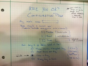
I haven’t worried too much about configuration. I sorta plan to do it via an HTML web page but I don’t have a particularly well thought out plan. I sketched up a possible webpage but plan to leave that very late in the game. If I’m designing for engineers, they’d probably rather change the parameters in code than have another piece to worry about (ok, that’s how I feel right now, I acknowledge it isn’t true for everyone).

AYOK configuration page

My brain is churning with all the things that need doing, that need considering. I think I’ll go solder parts. That should calm it down and clarify what the next steps are. Though, one of the next steps is to give Elizabeth working hardware, either tomorrow or next weekend. Ideally tomorrow.


h1

An LED in every plushie

April 10, 2014

Happily, one of my co-conspirators in the are-you-ok widget knows how to sew which means that we can progress to the next steps of development: productization.

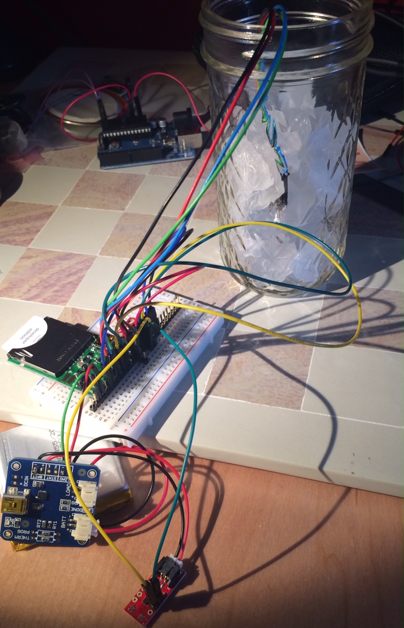
Here is what it looks like now.

naked gadgets

That is distinctly not cute. The jar of frosted glass is to hide the LED, so it doesn’t shine brightly in my eyes, the glass diffuses the LED. This is not a long term solution.

Right now the LED color is related to whatever the acceleration is: if the board is in the shown configuration, then the LED shines blue. If I tweak it to be on one edge or the other, it shines red or green. I enjoyed playing with the accelerometer to color translation but it was always just a diversion, to make sure I could see what I was doing.

So, why is the device going to have an LED? It is important for the user to know the unit received their attention. But I also need to show errors: low battery and no WiFi connection. With an RGB LED, my plan was:

  • GREEN or WHITE = acknowledge
  • YELLOW = low battery
  • RED = no WiFi

But now that we are talking about building the plushie, there were many good questions about the LED.

Three LED options

I am currently using a simple, standard RGB LED. If we use it, we’ll have to put it behind something (i.e. fabric that passes the light or milk jug material to diffuse the glow).

There is another option. I have small LEDs that are intended to be sewn into a device, to be shown. We could make them into coat buttons (one green, one yellow, one read).

When purchasing for this widget, I got a larger (no more powerful, just physically larger) LED with built in diffuser. This lets the light be a nose or center of a bowtie, something external to the device. I finally connected it today, it looks really nice (taking a picture of a lit LED is not a good way to see it, let’s just say that diffuser creates a gentle glow).

Gentle green glow

The LED will be on a long set of wires, 5-12″ depending on what is needed. The wire leads (shown in the glowy picture) will be clipped so there is little or no metal showing but there will be about an inch of rigidity after the LED.

Either of the two RGB LEDs can be hot glued to fabric or their wires can be sewn into the fabric. Either way will secure them. The single-color LEDs have those easy-sew holes.

The accelerometer will also be on a five-wire cable. It can be placed away from the rest of the electronics and the battery. This will let it be in the hand if we want the user to shake hands to wake up the widget. Or it could be on the head and the user can pat it. (And this is why an accelerometer is superior to a button. (I hope!))

The rest of the electronics (battery, charging board, electric imp board and the connections) should all be low in the creature, keeping its center of gravity low to allow for upright posture of the animal. Further, the back should velcro closed; we need to program the Imp for the WiFi of the house: we will need access to it.

Next, the system is battery powered (USB charging). The USB port (or cable) needs a way to be inserted, ideally without slipping out all of the other electronics guts.

A few more thoughts on making the plushie: child-safe material is critical, nothing flammable. I will make the electronics as safe as I can but having something like nylon which is both electrostatic and amazing flammable, well, I strongly prefer felt.